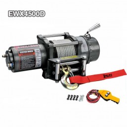
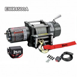
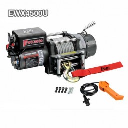
Electric UTV Winch 3500lbs
The EWP3500U electric UTV winch provides a 3,500 lb first-layer pulling capacity with automatic screw-cone braking and a two-bolt mounting interface for compatible vehicle recovery installations.
- Drive options: DC 12V or 24V permanent magnet motor configurations with a listed 170:1 reduction ratio.
- Mounting interface: Listed 79.5 mm mounting spacing with two M8 positions; confirm the installation drawing before fitment.
- U-version dimensions: Listed at 348 × 116 × 165 mm with a net weight of 10.0 kg.
- Rope and operation: Listed with 5.4 mm × 12.8 m wire rope, a free-spooling clutch and selectable control arrangements.
- OEM quotation: Irun Winch accepts OEM orders; provide voltage, quantity, mounting details and control or packaging requirements.

- Description
Electric UTV Winch EWP3500U with Two Bolt Mounting and Auto Brake
The EWP3500U electric UTV winch is rated at 3,500 lb (1,588 kg) on the first rope layer. Its listed specification combines a permanent magnet motor, a 170:1 reduction ratio, a free-spooling clutch and automatic screw-cone braking. A two-bolt mounting interface and U-version dimensions provide specific starting points for installation assessment.
- Rated first-layer pull: 3,500 lb (1,588 kg).
- Drive selection: DC 12V or DC 24V.
- Listed mounting spacing: 79.5 mm with two M8 positions.
Before selecting the winch, review the intended recovery task, electrical supply, working rope layer and supporting structure. The title capacity does not establish compatibility with every UTV.
Mounting Layout and U-Version Clearance
The EWP3500U uses the listed 3.13 in (79.5 mm), 2-M8 mounting arrangement. Buyers replacing an existing winch should compare the actual hole layout rather than assuming that another UTV winch uses the same interface.
- Hole layout: Check spacing and mounting orientation against the approved drawing.
- Installation envelope: Review the listed 348 × 116 × 165 mm U-version dimensions.
- Operating access: Allow clearance for the clutch, electrical connections and rope path.
The U version has different dimensions from the D and A versions in the comparison table. Confirm the complete model designation before approving a mounting plate or enclosure.
Free-Spooling Clutch and Automatic Braking
The feature list identifies a patented clutch structure, free-spooling operation and automatic screw-cone braking. The model instructions should define how these features are operated and maintained.
- Clutch operation: Request the engagement procedure and any restrictions on shifting.
- Brake maintenance: Review inspection and service instructions.
- Documentation: Request the patent reference if required for procurement review.
No lifting approval, unrestricted load-holding capability or continuous-duty rating is established by the supplied description. These capabilities should not be inferred from the automatic brake feature.
Product Specifications
The original specification table is retained below without changes to its data. The listed 12V and 24V motor values describe separate configurations.
| SPECIFICATION | |
| Rated line pull | 3500 lbs (1588 kgs) |
| Motor: permanent magnet | 12V:Input: 2.4kW / 3.2hp; Output: 1.0 kW/1.3hp |
| 24V:Input: 2.9 kW / 3.9hp; Output: 1.2KW/1.6hp | |
| Gear reduction ratio | 170:1 |
| Cable (Dia.× L) | Ø 7/32″×42.0′ (Ø 5.4mm×12.8m) |
| Drum size (Dia.× L) | Ø 1.46″×3.15″ (Ø 37mm×80 mm) |
| Mounting bolt pattern | 3.13″ (79.5 mm) 2-M8 |
The original metric and imperial rope diameter entries are preserved. Confirm the nominal rope specification, end connection and replacement requirements in the current technical documents before sourcing an alternative rope.
First-Layer Speed, Current and Rope-Layer Capacity
The following original table contains two independent data groups. The left side lists first-layer electrical performance, while the right side lists capacity and cumulative rope storage by layer. Entries sharing a row should not be interpreted as one combined operating condition.
| Pull Speed Amperes Volts First layer | Line Pull And Rope Capacity In Layer | ||||||
|
Line Pull Ibs (kgs) |
Line Speed Ft/min (m/min) |
Current A |
Layer of cable |
Rated line pull lbs(kgs) |
Total Rope On Drum ft (m) |
||
| 12V DC | 24V DC | 12V DC | 24V DC | 1 | 3500(1588) | 5.9(1.8) | |
| 0 | 10.5(3.2) | 10.5(3.2) | 20 | 16 | 2 | 2789(1265) | 13.5(4.1) |
| 1000(454) | 8.9(2.7) | 9.5(2.9) | 75 | 40 | 3 | 2319(1052) | 22.0(6.7) |
| 2000(907) | 7.5(2.3) | 8.9(2.7) | 130 | 75 | 4 | 1984 (900) | 31.2(9.5) |
| 3500(1588) | 4.6(1.4) | 7.5(2.3) | 200 | 120 | 5 | 1733 (786) | 42.0(12.8) |
Compare 12V and 24V at the Required Pull
Both voltage versions list a no-load speed of 3.2 m/min. At the first-layer 3,500 lb point, the listed values differ: 1.4 m/min at 200 A for 12V, compared with 2.3 m/min at 120 A for 24V.
- Voltage match: Select the version compatible with the intended electrical supply.
- Supply requirements: Review battery, cable, connection and protection specifications.
- Operating duration: Request the permitted duty cycle and cooling instructions separately.
The table provides listed performance points, not installation instructions or guaranteed results under every supply condition.
Use the Applicable Rope-Layer Rating
The pulling capacity decreases from 3,500 lb on the first layer to 1,733 lb on the fifth. The fifth-layer rope storage figure is 12.8 m, matching the listed rope length.
Assess the pulling task against the relevant layer capacity rather than applying the first-layer rating throughout operation. Retained wraps and rope handling must follow the model instructions.
EWP3500 Version Dimensions and Weight
The original comparison table distinguishes D, A and U versions. The U model is listed at 348 × 116 × 165 mm and 10.0 kg, while the D and A versions have a lower listed height.
| ITEM | EWP3500D | EWP3500A | EWP3500U |
| Overall dimensions | 13.2″×4.6″×4.4″ | 13.2″×4.6″×4.4″ | 13.7″×4.6″×6.5″ |
| (L×W×H) | 335mm×116mm×112 mm | 335mm×116mm×112 mm | 348mm×116mm×165mm |
| Net weight (Ibs) | 21.3 | 22.0 | 22.0 |
| (kgs) | 9.6 | 10.0 | 10.0 |
The listed dimensions and weight support initial fitment review. Obtain the approved drawing to confirm the mounting interface, control arrangement and clearance for the supplied configuration.
Control Options and Supplied Equipment Review
The feature list describes direct high-current switch control, an ATV handlebar switch, remote control through a control box and switch, and optional wireless operation. Detachable and separate control-box mounting are also listed as options.
- Operator control: Identify the required switch type and operating position.
- Control-box installation: Specify the preferred position for configuration review.
- Wireless option: Confirm whether wireless remote control is required.
- Equipment list: Request a clear record of supplied switches, controls and accessories.
The list does not establish that all control arrangements are supplied together or that each option applies to every EWP3500 version. Irun Winch should confirm the EWP3500U configuration and corresponding wiring diagram.
OEM Requests and Export Order Information
Irun Winch accepts OEM orders. Published voltage and control choices should be distinguished from branding, packing or structural requests that need additional assessment.
- Branding review: Provide logo files, marking locations and product label requirements.
- Packing review: Submit carton artwork, identification labels and export packing instructions.
- Technical review: Provide drawings for any proposed rope, mounting or control changes.
The supplied information does not confirm standard custom colors, alternative gear materials or unrestricted structural modifications. Irun Winch should identify approved options and any sample or development requirements in the quotation.
The listed supply information includes export carton packaging, ocean or air transportation and China as the place of origin. A CE certificate is listed; request the applicable documentation for the selected model. MOQ, production lead time and sample conditions are subject to confirmation.
Applications and Buyer Fit
This model can be evaluated for UTV recovery equipment projects where the pulling requirement, two-bolt interface and electrical supply match the confirmed specification.
- Vehicle equipment installers: Check mounting geometry, supporting structure and control access.
- Off-road distributors: Define voltage-specific configurations and accessory scope.
- OEM purchasing teams: Review drawings, electrical documents and packaging requirements.
Universal vehicle fitment, waterproof performance and lifting approval are not established by the supplied data. Requirements beyond the listed recovery application need separate confirmation.
Typical Fitment Review for a UTV Accessory Supplier
This illustrative scenario describes a procurement review, not a completed customer delivery. A UTV accessory supplier is considering EWP3500U as a replacement option for an installation with an existing mounting bracket.
Buyer Requirement: The supplier needs to confirm the two-hole interface, the U-version installation envelope and the required electrical configuration. The buyer also wants a defined control package so that installers do not assume every switch or wireless option is included.
Solution: Irun Winch would review the bracket drawing, vehicle supply voltage, control preference and target quantity. The review would compare the listed 79.5 mm mounting spacing and 348 × 116 × 165 mm dimensions with the proposed installation. Any mounting adaptation, control change or OEM label request would require approval.
Result: The intended outcome is a documented compatibility decision and an agreed supply specification before purchasing. This example does not claim a completed installation, verified field result or measured cost saving.
Electric UTV Winch Questions for Buyers
What distinguishes the EWP3500U mounting arrangement?
The specification lists 3.13 in (79.5 mm) spacing with two M8 positions. Confirm the complete layout in the installation drawing rather than assuming compatibility with a four-bolt plate.
How does the U version differ in size from D and A?
The table lists EWP3500U at 348 × 116 × 165 mm. The D and A versions are listed at 335 × 116 × 112 mm. Control configuration differences require separate confirmation.
Does the electric UTV winch retain 3,500 lb pull on all layers?
No. The table lists 3,500 lb on the first layer and 1,733 lb on the fifth. Use the capacity applicable to the intended working layer.
Which voltage should be ordered?
Select the version compatible with the vehicle's electrical supply. The published first-layer rated-pull points are 1.4 m/min at 200 A for 12V and 2.3 m/min at 120 A for 24V.
Is wireless control supplied as standard?
Wireless control is described as available. Confirm inclusion and compatibility with the selected control arrangement in the quotation.
Is a waterproof rating provided?
No IP rating is specified in the supplied description. Request supporting documents if the intended installation requires a defined environmental protection level.
What documentation is available for procurement review?
Request the current drawing, wiring diagram, operating manual and applicable CE documents. Any additional test reports should be confirmed for the ordered configuration.
What are the MOQ, lead time and sample terms?
These are not published in the supplied information. Irun Winch should confirm terms according to quantity, voltage, control package and OEM requirements.
About Irun Winch
Established in 1997, Zhejiang Jinhua Runye Tech. Co., Ltd. (Irun Winch) develops and manufactures vehicle winches and off-road accessories, including ATV and UTV models. Its manufacturing resources include precision machining equipment, motor testing equipment and comprehensive winch test systems. Irun Winch provides OEM service for international buyers and supplies products to more than 50 countries and regions.
Information for an EWP3500U Order Review
The following information helps Irun Winch prepare a configuration-specific quotation:
- Required quantity and DC 12V or DC 24V version.
- Vehicle application, existing mounting layout and available installation space.
- Switch type, control-box position and wireless control requirements.
- OEM logo, labeling or export carton requests, if applicable.
- Delivery destination and any sample or technical documentation requirements.
The quotation should confirm mounting compatibility, supplied controls, accessory scope, approved OEM details, MOQ and lead time.